[Unfinished] Dumping the firmware of a Landis+Gyr reading terminal

This whole project started as a curbside find: An abandoned power meter. Without much hesitation I picked it up.
After getting home and doing some research I found it was part of a metering system called SGP+M (Sistema de Gerenciamento de Perdas + Medição/System for Management of Losses + Metering). After more googling, I could find a manual for that system (read it here). It has many awesome stuff I’ll probably never get to see, so let’s just focus on the TLI.
If I’m not mistaken, TLI stands for “Terminal de Leitura de Informações/Information Reading Terminal”.
The board has these 3 main ICs:
- Z8 Encore! series microcontroller (Z8F0421), equipped with 4KB of flash.
- ATA5744N RF IC (RX Only, sadly).
- CF8566T LCD Driver.
There is a 6 pin debug header on the board. Here is the pinout:
- 1 - DBG
- 2 - VCC (capacitive dropper output)
- 3 - 3.3V
- 4 - NC
- 5 - NC
- 6 - GND
The DBG pin is Zilog’s authoral system for debugging their microcontrollers. It uses UART Half-Duplex for communication with automatic baud rate detection.
I found a post by Sean Young sharing their work on dumping a different Z8 Encore microcontroller. On this post there is a piece of code I managed to badly modify (with the help of ChatGPT) to not only transmit, but also receive the response data. It’s shown below, I flashed it on my STM32 Bluepill so I didn’t need logic level shifters.
#define pin PA0
#define BIT_DELAY 10  // microseconds per bit (your original timing)

// Your existing send_byte with small tweak
void send_byte(int b)
{
  pinMode(pin, OUTPUT);
  digitalWrite(pin, LOW);  // Start bit
  delayMicroseconds(BIT_DELAY);

  for (int i = 0; i < 8; i++) {
    if (b & (1 << i))
      digitalWrite(pin, HIGH);
    else
      digitalWrite(pin, LOW);
    delayMicroseconds(BIT_DELAY);
  }

  digitalWrite(pin, HIGH);  // Stop bit
  delayMicroseconds(BIT_DELAY);
}

// New bit-bang receiver matching that framing
int read_byte() {
  pinMode(pin, INPUT_PULLUP);

  // Wait for start bit (line goes LOW)
  while (digitalRead(pin) == HIGH);

  // Align to middle of first data bit
  delayMicroseconds(BIT_DELAY + BIT_DELAY / 2);

  int value = 0;
  for (int i = 0; i < 8; i++) {
    if (digitalRead(pin))
      value |= (1 << i);
    delayMicroseconds(BIT_DELAY);
  }

  // Optionally wait for stop bit, but ignoring it here
  delayMicroseconds(BIT_DELAY);

  return value;
}

void setup() {
  Serial.begin(115200);
  pinMode(pin, OUTPUT);
  digitalWrite(pin, HIGH);  // Idle HIGH
}


void loop() {
  Serial.println("Holding DBG LOW for manual power connection...");

  pinMode(pin, OUTPUT);
  digitalWrite(pin, LOW);
  delay(10000);  // <-- 10 seconds for you to connect target power

  Serial.println("Releasing DBG line...");
  digitalWrite(pin, HIGH);
  delay(1);

  Serial.println("Starting communication sequence...");

  // Your existing command sequence
  send_byte(0x80);
  send_byte(0x0B);
  send_byte(0x00);
  send_byte(0x00);
  send_byte(0x20);
  send_byte(0x00);

  Serial.println("Switching to receive mode...");

  pinMode(pin, INPUT_PULLUP);
  delayMicroseconds(50);

  for (int i = 0; i < 1024; i++) {
    int b = read_byte();
    Serial.print("RECV 0x");
    Serial.println(b, HEX);
  }

  Serial.println("Done.");
  while (1);
}
Sadly all I got was 0xFF, which means the MCU has read protection enabled. Scrolling further on Sean’s post, we can see they also got it, but that isn’t the end of it. Zilog has an application note named AN0117 that explains how to do gang programming on Z8 microcontrollers using something called the BYPASS mode.
Sean built a kernel driver that was meant to be used on a raspberry pi, but since I don’t have one in hands I built my own crude dumper. Code avaiable here:
The code is available on a GitHub repository on my profile.
The thing is: it didn’t work. I am a terrible coder, i did my best to follow the flowchart that’s on the application note, and couldn’t find the issue, this code spits out garbage. Note that I skiped the PB3 sync part because my microcontroller doesn’t have PB3.


If anyone reading through this would like to take a look and find the issue, please contact me on my discord @housey2k
While the idea was keeping the original board without replacing anything, turns out it’s hell to play with cursed MCUs, so with this and previous projects, I learned a lesson: Not wasting time with shitty microcontrollers
I don’t know what makes companies choose shitty microcontrollers that are expensive, locked and worse than an Arduino or STM32, but very likely they are getting these microcontrollers for a crazy discount because no one wants them
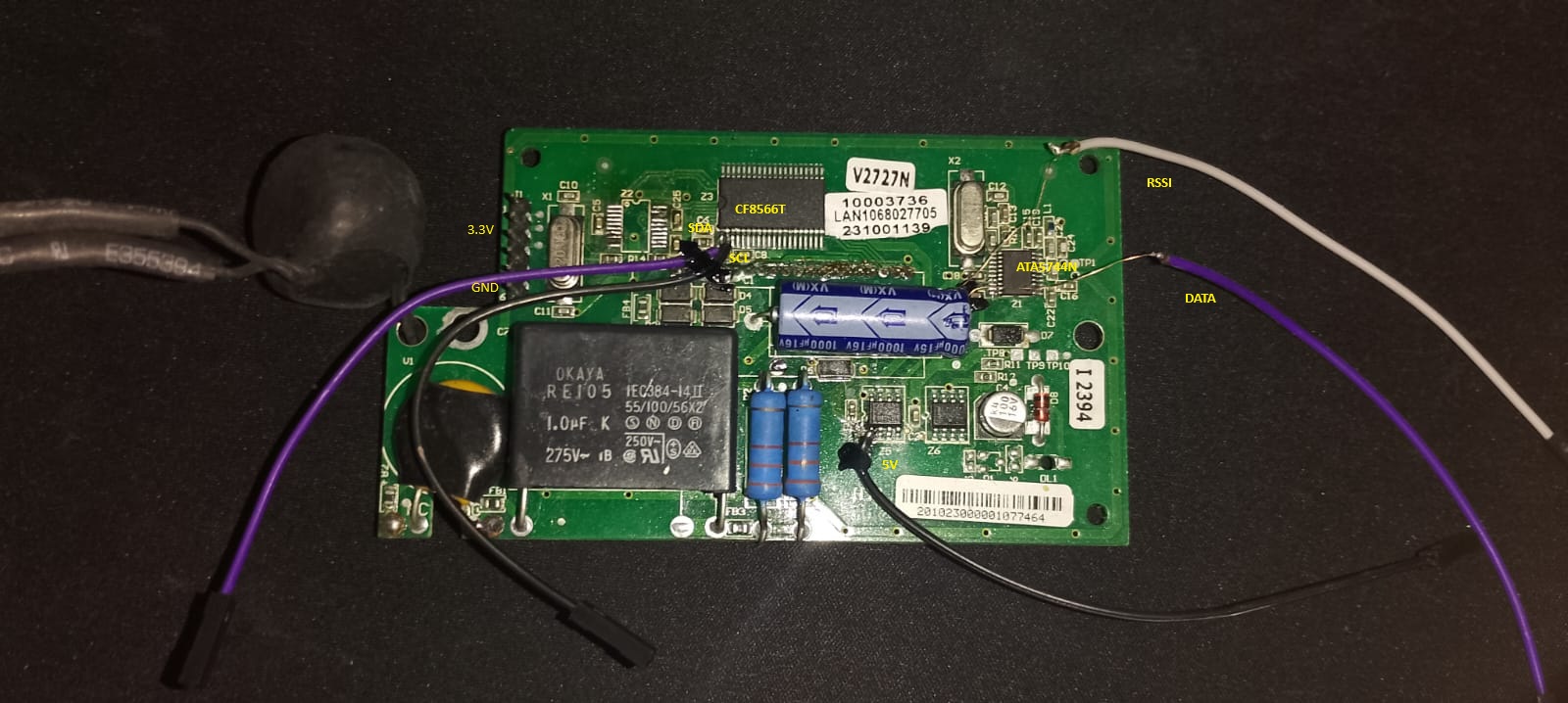
With my board with the Z8 chip already removed, i soldered jumper wires to some points of the board to create a little STM32 modchip for it, these points being 5V, LCD_SCL, LCD_SDA, RF_DATA, RF_RSSI, I already have 3.3V and GND from the debug header.
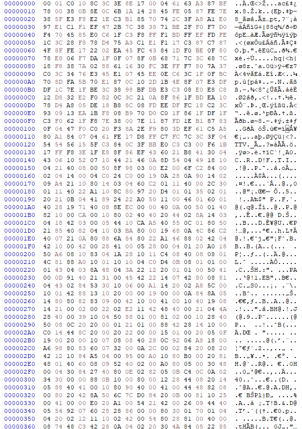
After writing the firmware available here on my STM32 to decode the data that’s being spit out by the RF chip (which seems to be ASK-PWM according to ChatGPT’s analisys), I managed to get some data that’s either encrypted or it’s junk, shown on the image below, sadly i lost the bin file so I gotta do a new capture