Projects by a kid
I was a kid with unsupervised internet access, and I had contact with electronic stuff since my dad fixed computers, eventually I wanted to learn on my own, and I studied and tried stuff on simulators I could find on the internet, like TinkerCAD and flash player things.
Eventually I had the bare minimum of knowledge to create my own stuff, even though I never built any of my designs because I didn’t have a lot of money as a kid, I tried some stuff on CAD software, and I wanted to share a bit of my first designs
FurModularity
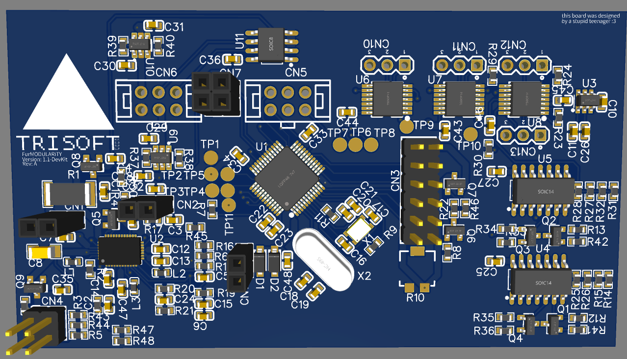
FurModularity was a system I designed that was a reimagining Zack Freedman’s Singularitron, if I’m building this, I need to review the hardware I designed back then and probably fix some beginner mistakes and cut costs, but I am pretty sure the board would work as is (even if not fully operational)
The name FurModularity means “For Modularity”, meaning it’s a modular system, the prefix “Fur” is because of furry, this system could be connected to some fursuit like a protogen to help with control for fans/led/idk
Here are some of the hardware features:
- The main microcontroller is an STM32F103, cheap and powerful
- LCD communicates on parallel 4-bit mode
- My system takes up to 4 modules, they communicate via 4-wire SPI and powered via 3.3V and 5V power supplies
- The PMIC is a LTC3586, The same used on the Singularitron, One thing I really like about this PMIC is the fact that you can set it up in a purely analog way, no programming means less expensive/proprietary tools (yet a few extra cents on passives) and straightforward troubleshooting
- Audio circuit with two inputs and two outputs with software controlled mixer, hardware is only digital potentiometers, opamps and multiplexers, no complicated ICs
Some things I would change while I review my design to write this article are:
- Tweak some values on BJT base resistors
- Replace the battery level ADC with a voltage divider going into some analog input of the MCU
- Replace some of the DuPont connectors with JST due to size and tightness
- Change for I2C LCD
SmartTDCS
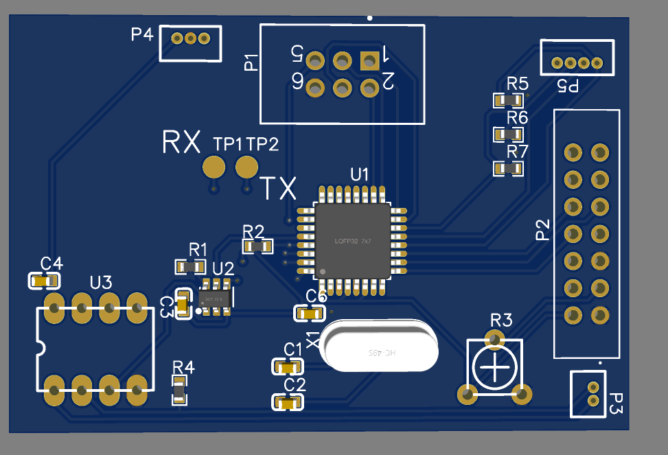
SmartTDCS was a medical device I designed (that now I realize design mistakes, and potential dangers). Althought I am even more sure it would work since it’s a really simple board
If you don’t know what tDCS is, it’s pretty cool, you should check it out;
Here are some of the hardware features:
- The main microcontroller is a ATMEGA328PAU, pretty simple, this was the first PCB i ever designed
- LCD communicates on 4-bit mode
- Uses a MCP4725 DAC
- LM358N for constant-current supply
- Dual power supplies of 30V and 5V
- 3 Buttons for control (up, down, Press Change setting/Hold Start)
And the things I would change:
- Replace the pull down resistors for the AtMega’s internal pull up
- Change for I2C LCD
- Add input supply protection
- Change THT Op-Amp for SMD