An Attempt: Hacking an MT1389-Based CD/DVD Drive

Recently, I dug out a CD/DVD player from my scrap pile, though I no longer have the model info (I tossed the casing a while back and just kept the boards). The unit was missing the actual optical drive, but it still had the VFD display, mainboard, and SMPS board intact.
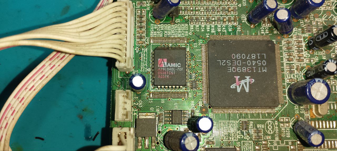
The goal of this project is to dump and analyze the firmware, which I believe is stored in the A29L040L EEPROM located next to the main MT1389QE chip. I don’t have a parallel programmer at the moment, so I’m waiting on an STM32 Bluepill to arrive, which I plan to use as a programmer. I’m also planning to install a PLCC32 socket on the board so I can remove the EEPROM easily without having to keep reheating the board.
There’s a connector labeled CN3 that looks like a UART interface, but so far I haven’t seen any data coming from any of the pins.
Here are some documents I found during OSINT that might be useful for understanding or reverse engineering the system:

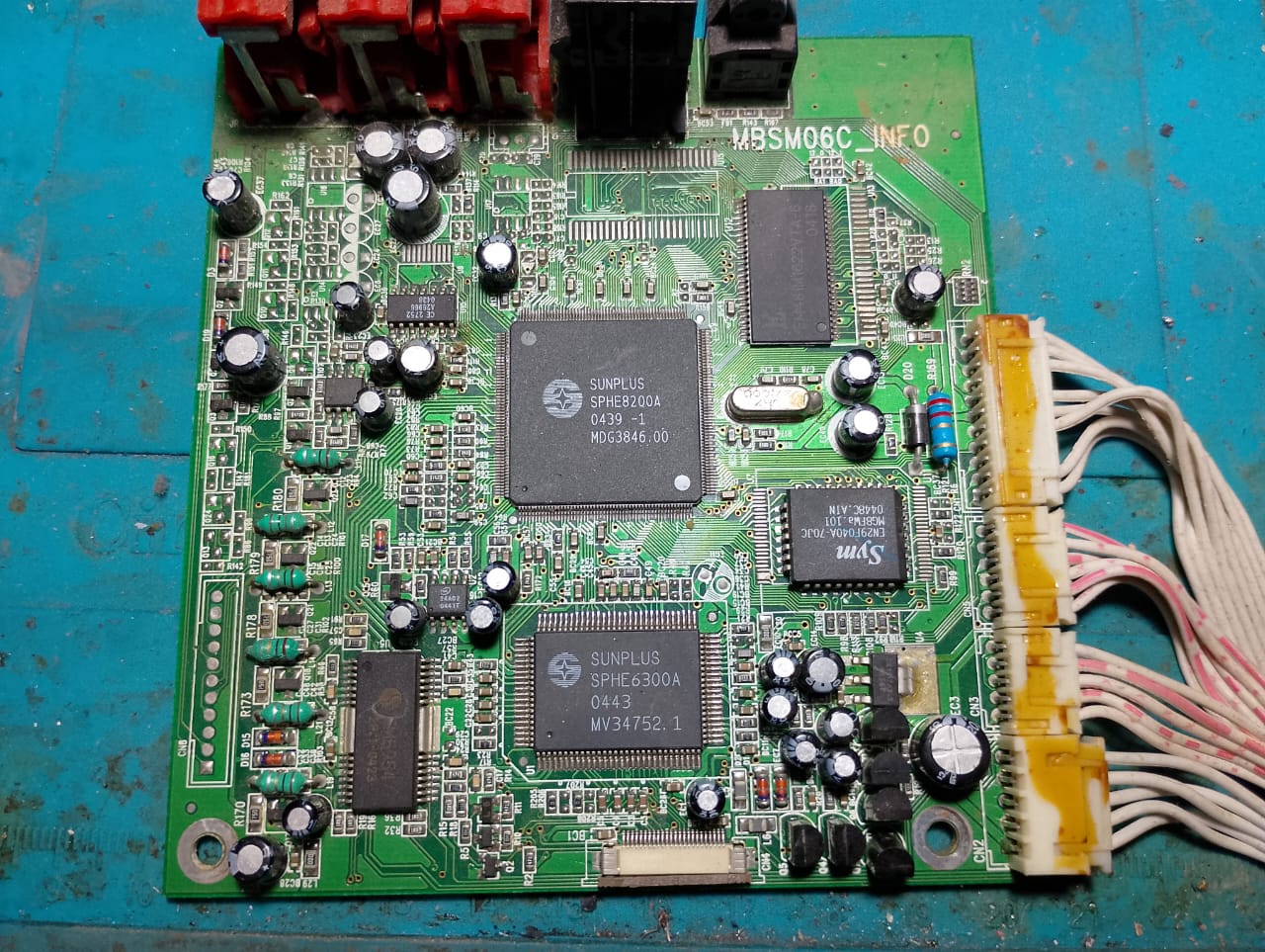
I also came across another CD/DVD player board based on a different IC—the SPHE8200A, which, like the MT1389, is RISC-based. This board doesn’t have a VFD, but it does include two flash memory chips: a PLCC32 and a SOP48. I’m not entirely sure of their roles, but my guess is that the PLCC32 holds the low-level firmware, while the TSOP28 contains a higher-level OS or application layer.
There’s also an SPHE6300A chip on this board. I wasn’t able to find much documentation on it, but given that it’s connected to the FFC that runs to the laser head, I suspect it’s handling the optical pickup functionality.
Since both boards use CPUs based on the same architecture, they likely share the same instruction set and could potentially be debugged via JTAG in a similar way. For now, I’m focusing on the MT1389QE-based board—it’s simpler, with only one EEPROM and a cleaner layout to work with.
Update: I’ve decided to completely abandon this project. The UART header doesn’t output anything during boot, and the JTAG interface appears to be repurposed as GPIO, making proper debugging impractical. The firmware is stored in a PLCC32 parallel flash, which I can’t read without desoldering or investing in new sockets and a programmer — and frankly, it’s not worth the hassle for something this minor.
I managed to reuse the VFD screen, I used the original SMPS board, but replaced the DVD motherboard with an arduino (Measuring the data pins I see 5V, which is weird considering the SoC was 3.3V)
I’m using a library made by Liviu Istrate, download available on their post and on my website as a backup
There’s a video below scrolling some text